tutorial
How to Make an LED Light Up and Blink Using Arduino with Connections
Led Stands for -“Light Emitting Diode”
A light-emitting diode is a two-lead semiconductor light source. It is a p–n junction diode that emits light when activated. When a suitable current is applied to the leads, electrons are able to recombine with electron holes within the device, releasing energy in the form of photons.
What is Resistor ?
A resistor is a passive two-terminal electrical component that implements electrical resistance as a circuit element. In electronic circuits, resistors are used to reduce current flow, adjust signal levels, to divide voltages, bias active elements, and terminate transmission lines, among other uses.
A resistor is a passive two-terminal electrical component that implements electrical resistance as a circuit element. In electronic circuits, resistors are used to reduce current flow, adjust signal levels, to divide voltages, bias active elements, and terminate transmission lines, among other uses.
Use of Resistors in Arduino
When building our Arduino projects, we use resistors to limit the amount of current going to certain components in the circuit, such as LED's and
integrated circuits.
Hardware Required
1. Arduino or Genuino Board
2. LED
3. 220 ohm resistor
ELECTRICAL SIGNALS
The Arduino communicates with modules and sensors by switching on and off electrical current. It’s very similar to the one’s and zero’s in binary
code. When current is switched on, it’s known as a “HIGH signal”. That’s comparable to the “one” in binary code. When the current is switched
off, that’s a “LOW signal”, which is similar to the zero in binary code. The length of time the current stays on or off can be changed from a
microsecond up to many minutes.
CONTROLLING THE ARDUINO’S LED
To turn on an LED, the Arduino needs to send a HIGH signal to one of it’s pins. To turn off the LED, it needs to send a LOW signal to the pin. You
can make the LED flash by changing the length of the HIGH and LOW states.
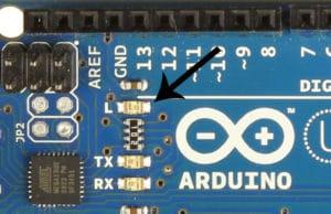
The Arduino has an on-board surface mount LED that’s hard wired to digital pin 13. It’s the one with an “L” next to it:
Getting Started with the Arduino - Arduino Uno LED
To get this LED flashing, upload the “Blink” program to your Arduino:
Code:
void setup()
{
pinMode(13, OUTPUT);
}
void loop()
{
digitalWrite(13, HIGH);
delay(1000);
digitalWrite(13, LOW);
delay(1000);
}
The LED should now be blinking on and off at a rate of 1000 milliseconds (1000 milliseconds = 1 second).
The delay() function on line 6 tells the Arduino to hold the HIGH signal at pin 13 for 1000 ms. The delay() function on line 8 tells it to hold the LOW signal at pin 13 for 1000 ms. You can change the blinking speed by changing the number inside the parentheses of the delay() functions.
Output
Led will turn on and off for 1 seconds(1000 milliseconds).
Connection Diagram
Schematic Diagram
Reference:
1. pinMode (): Configures the specified pin to behave either as an input or an output.
2. digitalWrite (): Write a HIGH or a LOW value to a digital pin. If the pin has been configured as an OUTPUT with pinMode(), its voltage will be set to the corresponding value: 5V (or 3.3V on boards) for HIGH, 0V (ground) for LOW
3. delay (): Pauses the program for the amount of time (in milliseconds) specified as parameter. (There are 1000 milliseconds in a second.)


No comments:
Post a Comment